SESAmpacity
SESAmpacity is an effective tool for performing ampacity, minimum conductor size and temperature rise calculations for buried and aboveground conductors based on the conductors’ thermal characteristics. SESAmpacity also calculates the temperature rise of the HVDC land ground electrode.
SESAmpacity computes the minimum conductor size needed to withstand a given current. It determines the conductor ampacity as well as the temperature rise of bare buried conductors during fault conditions and overhead conductors during steady-state or fault conditions.
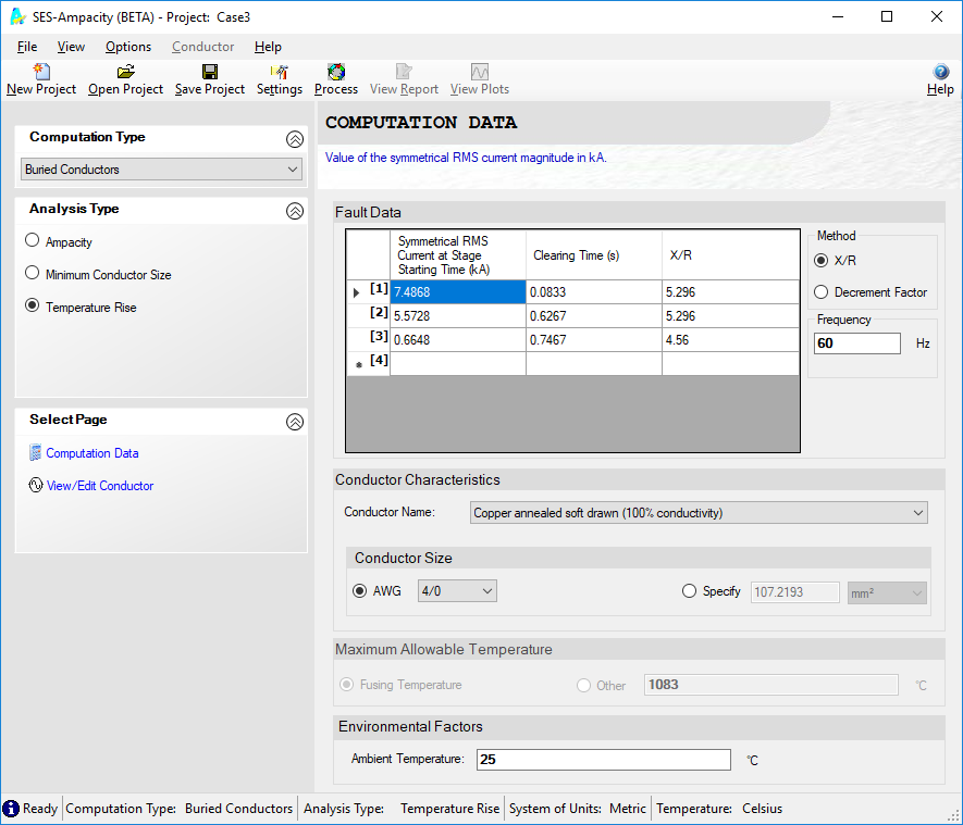
Traditional fault condition approaches and previous versions of SESAmpacity consider a single set of data for fault current and the X/R ratio for a given fault duration. The current version of SESAmpacity accounts for faults consisting of multiple fault current levels, with various clearing times. Multi-stage faults can be analyzed accurately with SESAmpacity.
Technical Highlights
Conductor selection is a major factor that must be taken into account during the process of grounding or transmission line design. It is important that the most appropriate conductor type and size be selected for optimum operating efficiency. The electrical and thermal properties of conductors dictate the choice of conductor type and size for a given design. Factors such as environmental effects, electrical loss, current loading and many others must often be considered in the process.
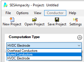
SESAmpacity offers three calculation modules that allow you to quickly estimate the required size of buried conductors, to simulate the thermal behavior of aboveground conductors, and calculate the temperature rise of the HVDC land ground electrode.
Several types of databases store the properties of conductors related to their thermal, electrical behavior for a large collection of conductors, the heat capacitivity of soil and the thermal conductivity of soil. The conductor database can be extended with your own conductor data if the predefined ones do not meet your needs.
A user-friendly interface and facility of data entry make SESAmpacity an efficient and useful tool for the conductor selection process in grounding and transmission-line design applications.
SESAmpacity has three modes of operation:
Bare Buried Conductor Module
The Bare Buried Conductor module computes the following quantities during fault conditions:
The assumptions made in the calculations are as follows:
The basic equations used in this module are provided in ANSI/IEEE Standard 80 for the calculation of ampacity for symmetrical currents. To account for asymmetrical current characteristics (i.e., DC offset), the symmetrical current is increased in accordance with the decrement factor presented in the same standard.
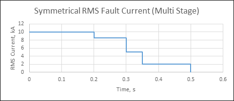
An accurate calculation of the asymmetrical RMS fault current is an important step in the determination of the temperature rise of conductors during a fault or when sizing ground conductors. As detailed in IEEE Std. 80, the standard way to calculate the asymmetrical RMS fault current (which is used in the previous version of SESAmpacity) assumes that the symmetrical RMS fault current and the system X/R ratio are constant over the entire fault duration. This can be referred to as a single-stage fault.
However, in reality, a fault can be fed from various substations, which may have different fault clearing times, and the value of the system X/R ratio can vary during the fault. This can be referred to as a multi-stage fault. The single-stage fault approach cannot be applied directly to this scenario, as there exist significant differences in the symmetrical RMS current over the duration of the fault.
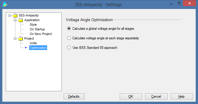
The SESAmpacity computation module accounts for such multi-stage faults when calculating the asymmetrical RMS fault current. The user decides if they want to use this multi-stage approach or maintain a conservative approach using the single stage approach described in the IEEE-80 standard.
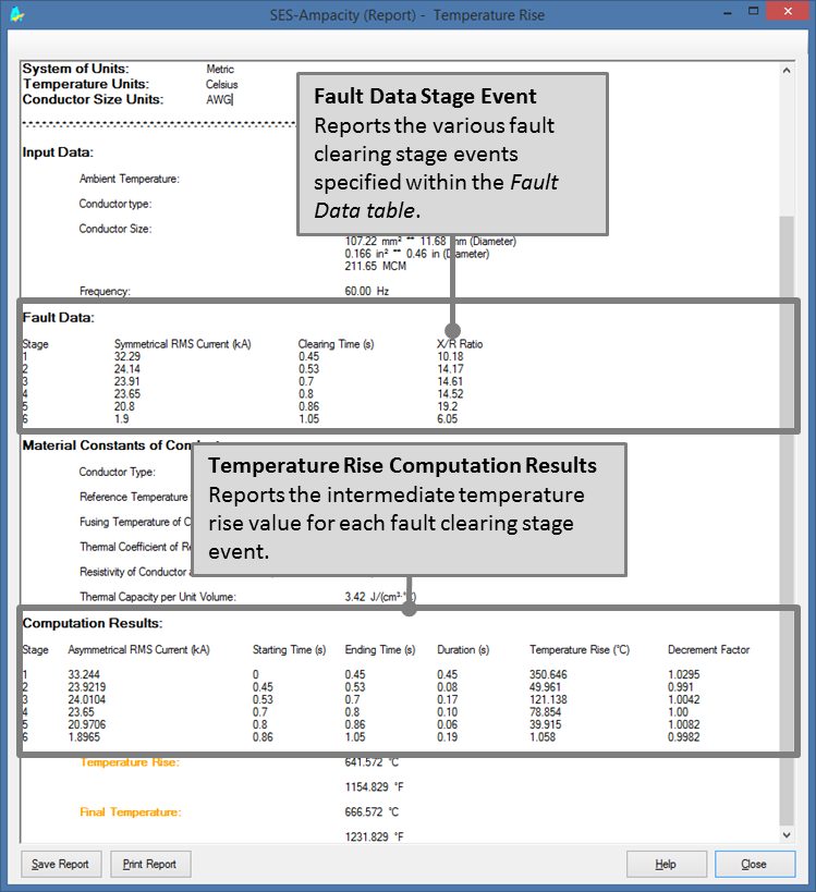
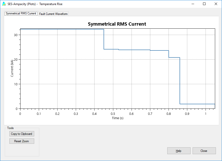
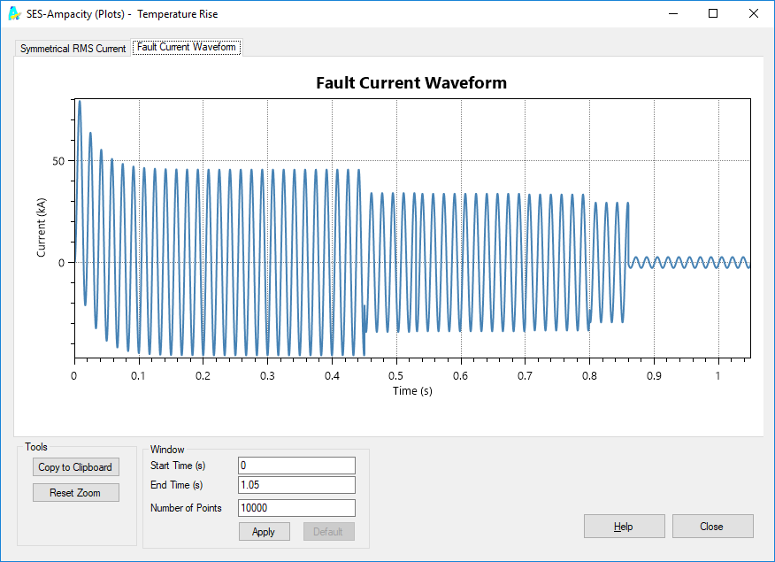
Computation Results
A comprehensive report and revealing plots are available once computations are completed. For example, intermediate temperature rise values are reported in the analysis report for each stage.
Bare Overhead Conductor Module
The temperature of an overhead conductor that carries an electrical current is a function of not only the magnitude of this current but also of several environmental factors that influence the amount of solar heating and the ability of the conductor to dissipate heat by convection and radiation.
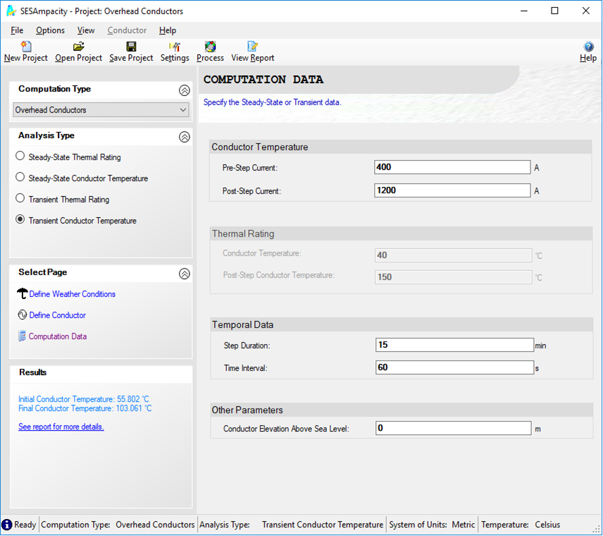
The Bare Overhead Conductor module includes computation methods, based on the procedure described in IEEE Standard 738, relating electrical current to conductor temperature that are used in either of the following ways:
For those two cases, SESAmpacity can perform four different computations related to the thermal capacity of bare overhead conductors:
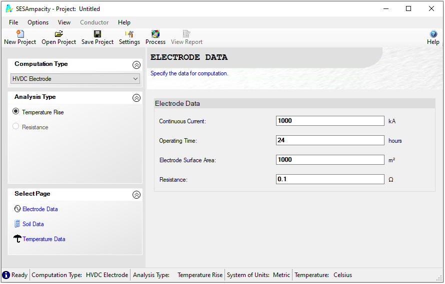
HVDC Electrode Module
The design of an HVDC electrode generally takes into consideration various aspects. The calculation of the temperature rise is an important step in the design of an HVDC ground electrode. HVDC networks permanently or temporarily use ground electrodes to conduct currents in the earth as a return circuit, and when this happens during full load operations, a high current will pass through the ground electrode for a sustained duration. Soil is a poor thermal conductor, and the current density in the earth near an HVDC ground electrode can be quite high. When the temperature of the soil increases the water in the soil vaporizes, its moisture content is reduced, and as a result, there is an increase in soil resistivity, which could endanger equipment as well as personnel near the HVDC electrode.
The HVDC Electrode module is used to calculate the temperature rise of the HVDC land ground electrode. The parameters required to carry out the computation are grouped into three data sets: