RowCAD
ROWCAD is the fully interactive graphical system specification environment for Right-of-Way Pro. You can specify all foundational data for the model and proceed directly to a circuit creation, all in this user-friendly environment.
ROWCAD has now become the standard Right-of-Way Pro model specification environment and continues to grow.
ROWCAD not only assists with the system data specification, it also has a powerful integrated segmentation algorithm that automatically establishes the zones of inductive coupling to create a representative circuit model. ROWCAD also allows you to specify the additional complex conductor arrangements needed for the final Total Interference (inductive, capacitive and conductive coupling) model.
In its original form in 2011, ROWCAD provided a visual interface and a powerful path segmentation algorithm to help specify complex network geometries. Over the years, ROWCAD saw substantial enhancements, which addressed many enhancements directly. ROWCAD is now capable of specifying in full practically all system configurations, with more flexibility and ease, and all with a more complete ROW integration. SES added a wealth of design tools and model validations, all to make the design process more ergonomic and robust.
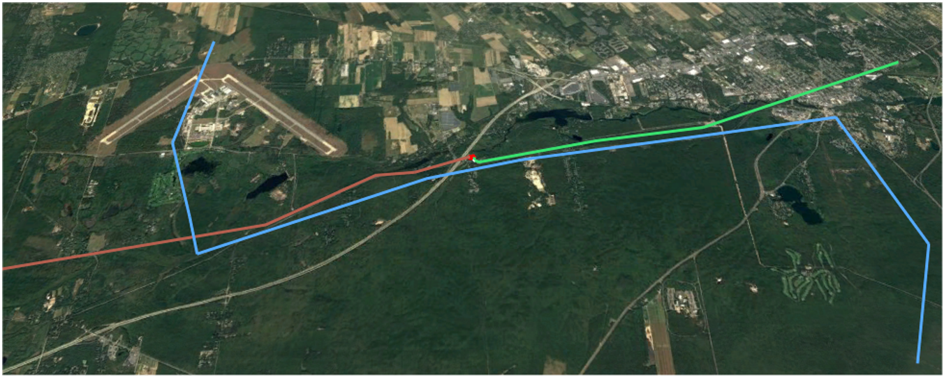
Incorporate Map Data
Import path center line data from SES compatible data types or DXF (via SESConverter), or even directly from Keyhole Markup Language files (KML).
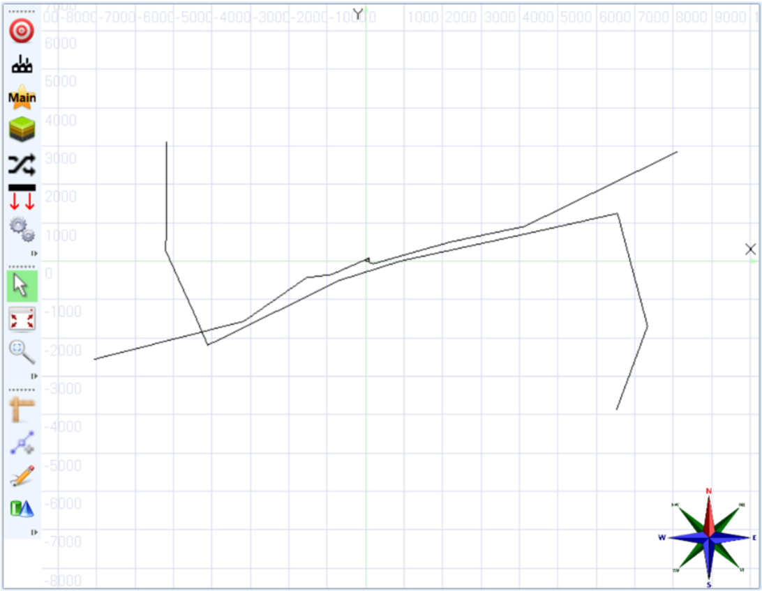
Intuitive and Visual Data Specification
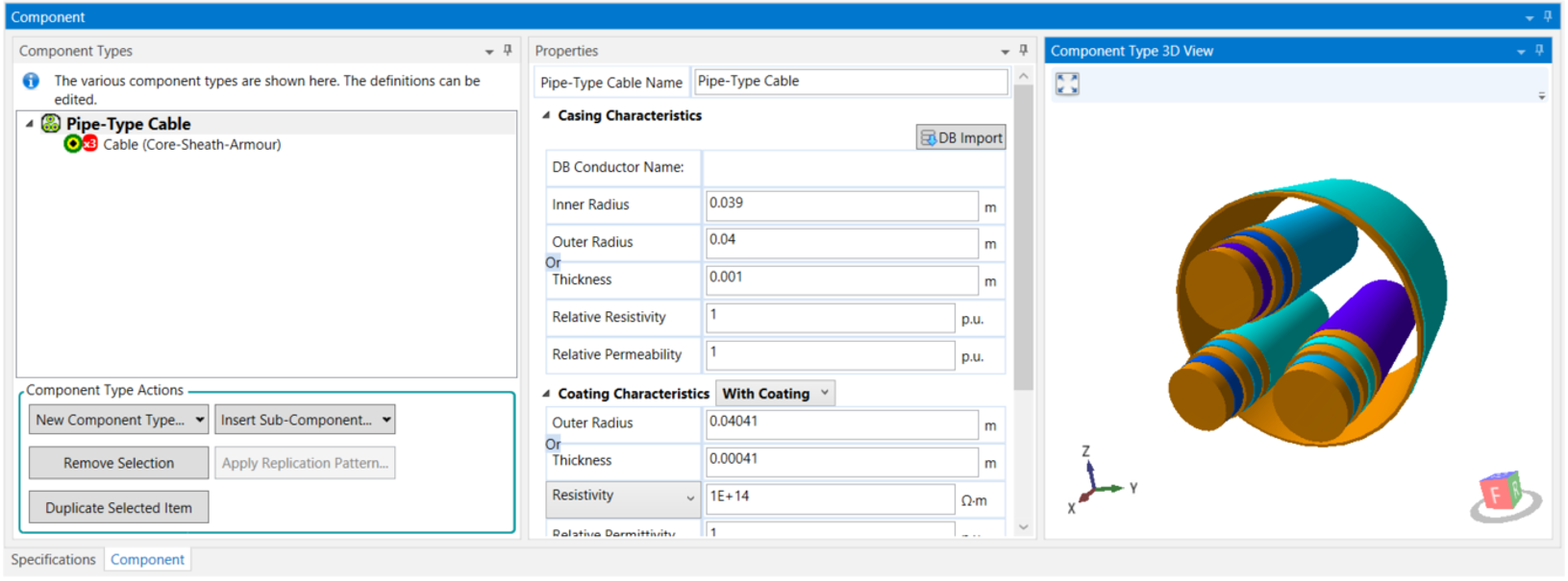
Graphically define conductor characteristics and path cross-sections with SESCrossSection.
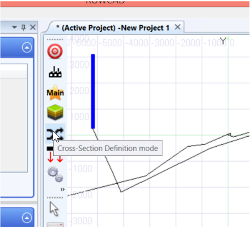
Graphically assign cross-sections, soil regions and circuit parameters directly on the graphical system viewer.
Tabular data specification inputs are also available, all to adapt to your preference or your specific project needs.
Define soil models, phase information, and system energization, or even annotate the model view with notes to better find your way around the model.
Designer Helper Tools
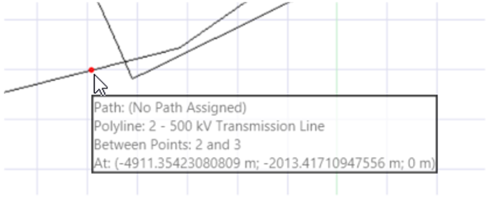
Use the proximity locking tool to help find exact locations along your defined paths:
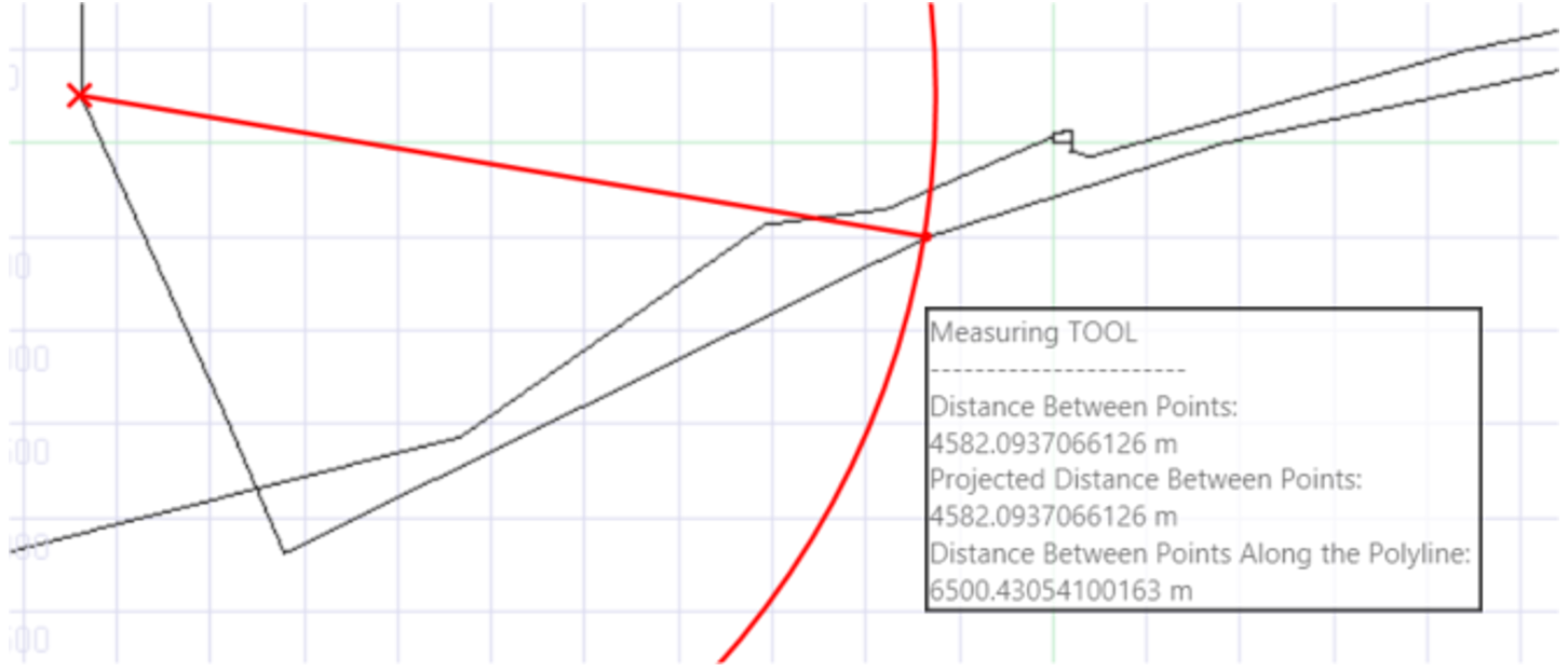
Measure the length of a straight line or the distance along polylines:
The model view can be rotated or panned as you wish.
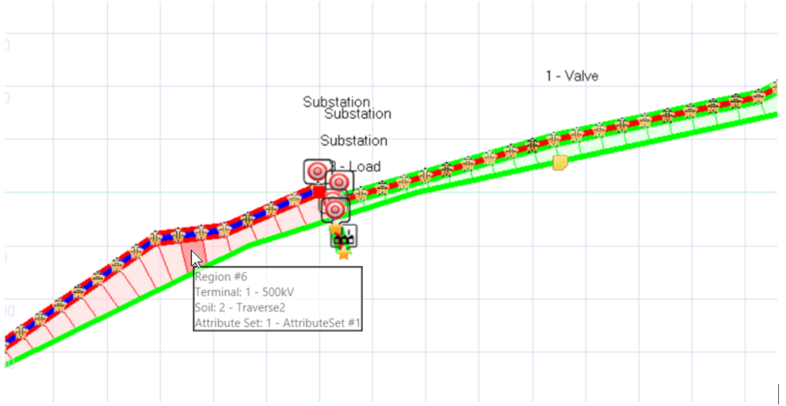
Finally, automatically have the program determine the zones of inductive interference in order to create an accurate circuit model:
Full Right-of-Way Pro integration
Import part, or the entirety of system data into Right-of-Way Pro to create a circuit model and move on with your study.
A Project Management Framework for ROWCAD
ROWCAD has a convenient project-scenario based structure for managing multiple related models, has a compact file format, and is fluidly integrated with the core computation module Right-of-Way.
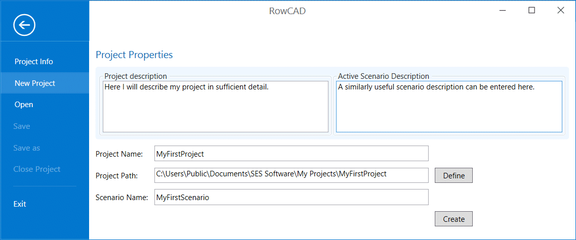
The project and scenarios are managed from the Project Info screen:
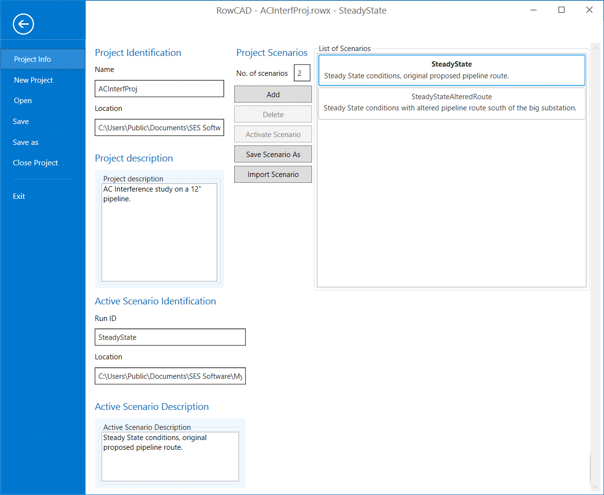
The Open portion of the Project screen provides convenient links to recently edited projects or scenarios or a set of convenient standard folder locations.
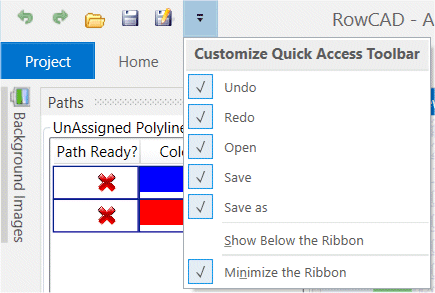
Once a scenario has been created, a ribbon-style menu is available. First, at the very top of the screen, convenient shortcut buttons to Undo , Redo , Open , Save and Save As are available.
Second, a ribbon provides access to a wealth of tools without having to go through expandable menus. The ribbon is divided in Home , Options , and Help tabs.
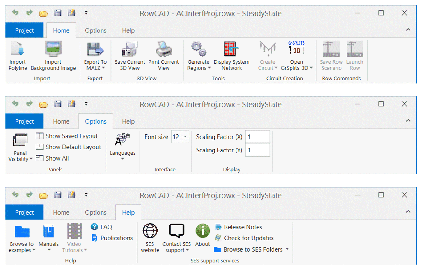
While providing an intuitive graphical interface, ROWCAD is fully integrated with the Right-of-Way Pro. Once all necessary input data have been specified, and Generate Regions run, a powerful set of new buttons become available, i.e., Create Circuit , Open GRSPLITS-3D , Save Row Scenario . The Launch Row button becomes available once either the circuit creation has been completed, or once the scenario has been saved to ROW.
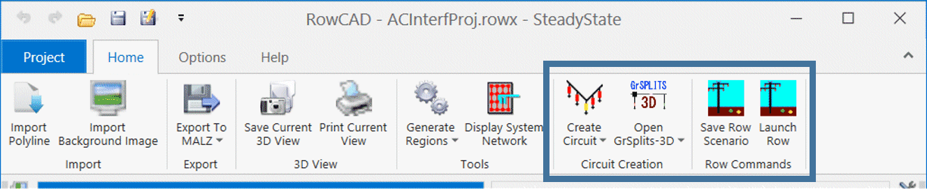
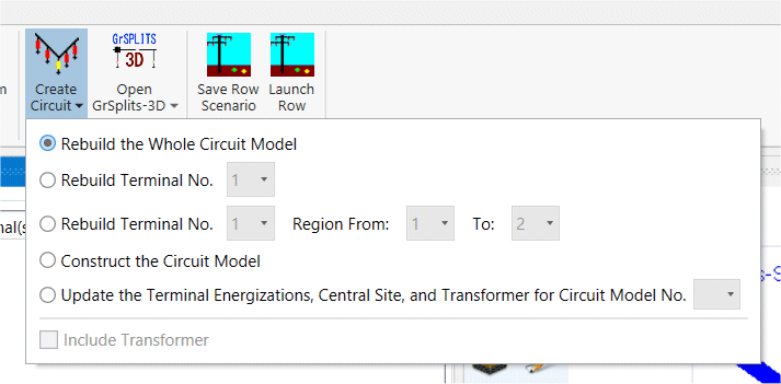
The Create Circuit button will automatically create a ROW project file at the same level as the ROWCAD project file.
The Create Circuit button also includes the circuit creation options ROW offers.
You can now essentially specify your entire system directly in ROWCAD in a compact form, and complete the circuit creation with an economy of actions and all while maintaining an organized and self-consistent folder structure, with no additional effort.
Complete Model Definition Directly in ROWCAD
Central Site Impedances Definition
The Central Site grounding resistance and reactance can be directly defined in ROWCAD from the Central Site and Terminals panel.
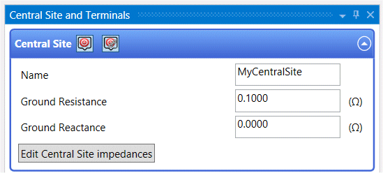
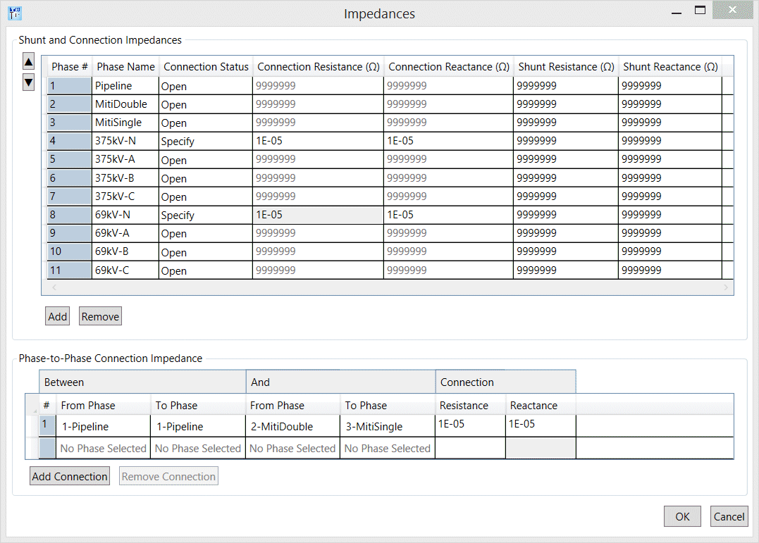
The Edit Central Site Impedances button opens a screen in which the Connection Impedances between each individual phase and the Central Site ground, the shunt impedance for each phase at the Central Site location, and phase‑to‑phase connections at the Central Site location can be specified.
Soil Model Definition Screen
Soil models are stored directly in the ROWCAD scenario, which keep files well-organized and transportable.
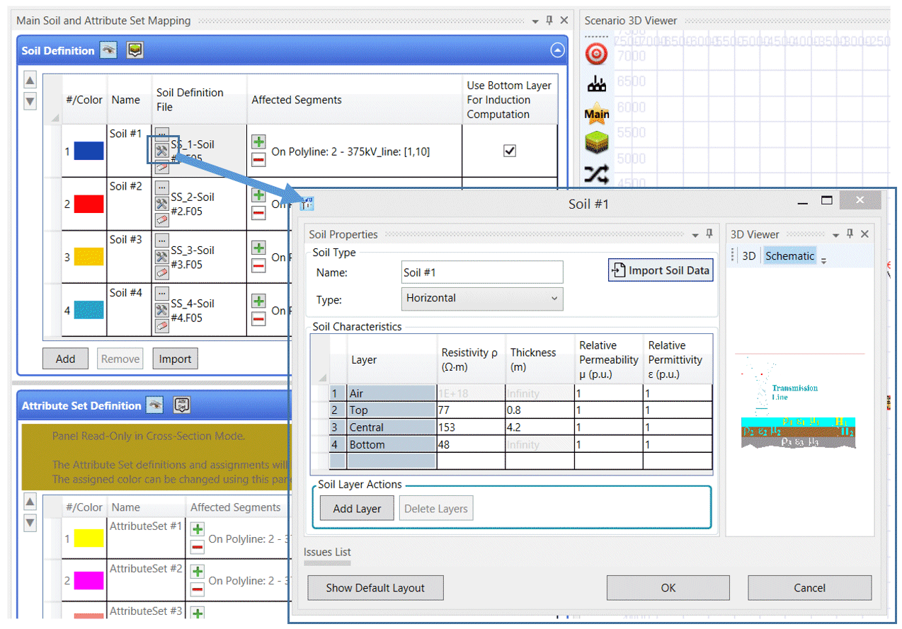
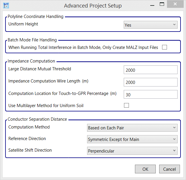
An Advanced button accesses the screen which allows the adjustment of the computation settings.
OK/Cancel on all Windows
ROWCAD often involves many secondary screens and windows to complete the input of data, and these now are all equipped with OK and CANCEL buttons.
New and Improved Design Tools
Entities Related Tools
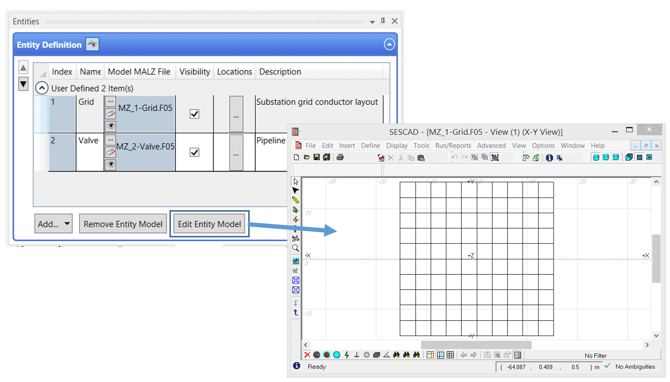
Entities in ROWCAD can be used to define notes, as well as observation points and conductor configurations to be incorporated in the MALZ template file to be used for a Total Interference analysis.
Entities can be defined and edited by opening the SESCAD interface directly from ROWCAD. Simply save your design before closing SESCAD and the entity has been defined.
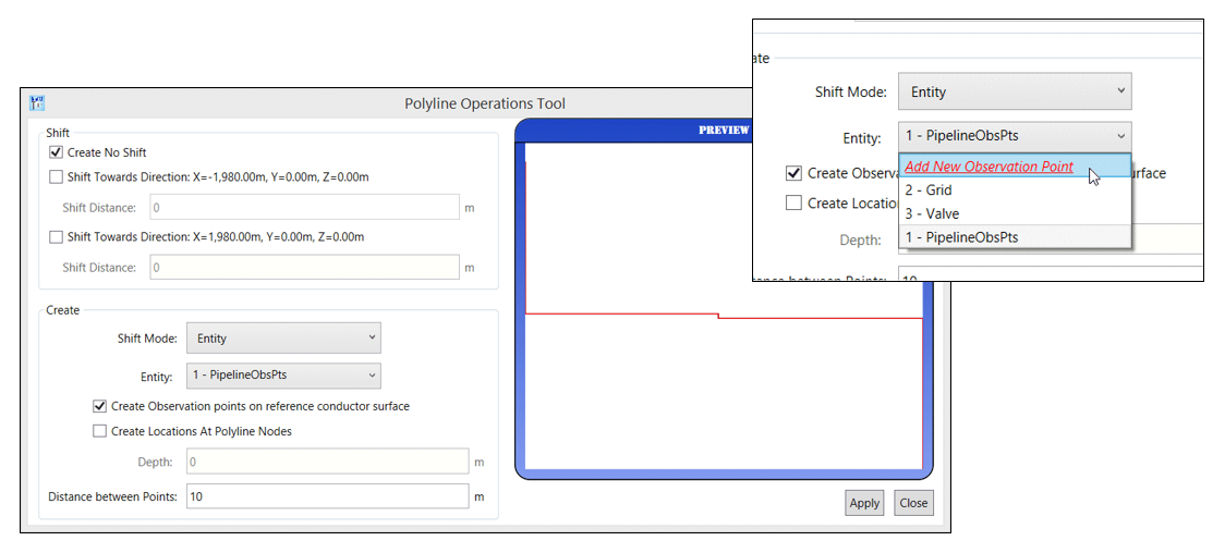
The Polyline Operations tool has the capability to define observation points along a polyline with a customizable point separation, and the capability of defining observation points on the reference conductor surface.
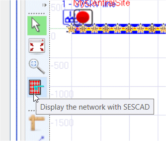
ROWCAD is also now outfitted with Display the Network in SESCAD tool in the viewer toolbar, much akin to the Plot Network found in ROW.
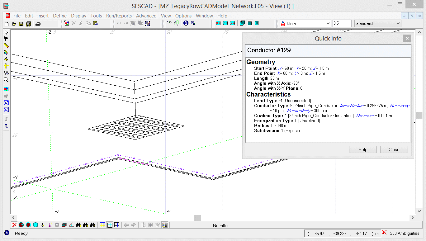
This display is substantially more informative in that it displays not only the system as it relates to polylines (including detailed conductor types), but also shows the entities in their correct locations, and also shows simplified tower models where Tower type points are found along the polyline.
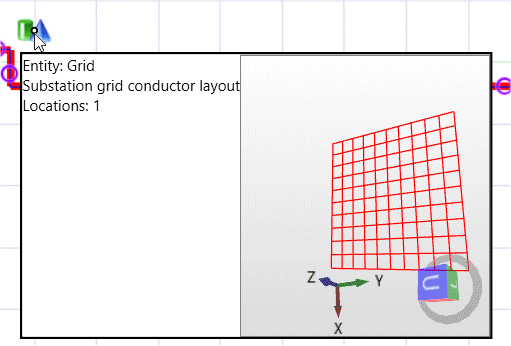
Entities can also now be selected and moved (by clicking and dragging) with the cursor. Moreover, a 3D preview of the entity model is displayed if the cursor hovers over the entity location in the viewer.
All these tools allow for the complete and efficient design of the conductive interference MALT model directly in ROWCAD.
Polyline and Cross-Section Related Tools
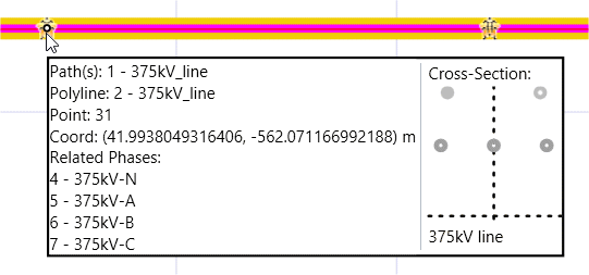
ROWCAD now includes an enhanced visual display of the properties of cross-sections assigned to portions of a polyline. The tooltip displayed when the cursor hovers over a polyline shows the phases associated to the polyline, as well as a 2D view of the cross-section assigned.
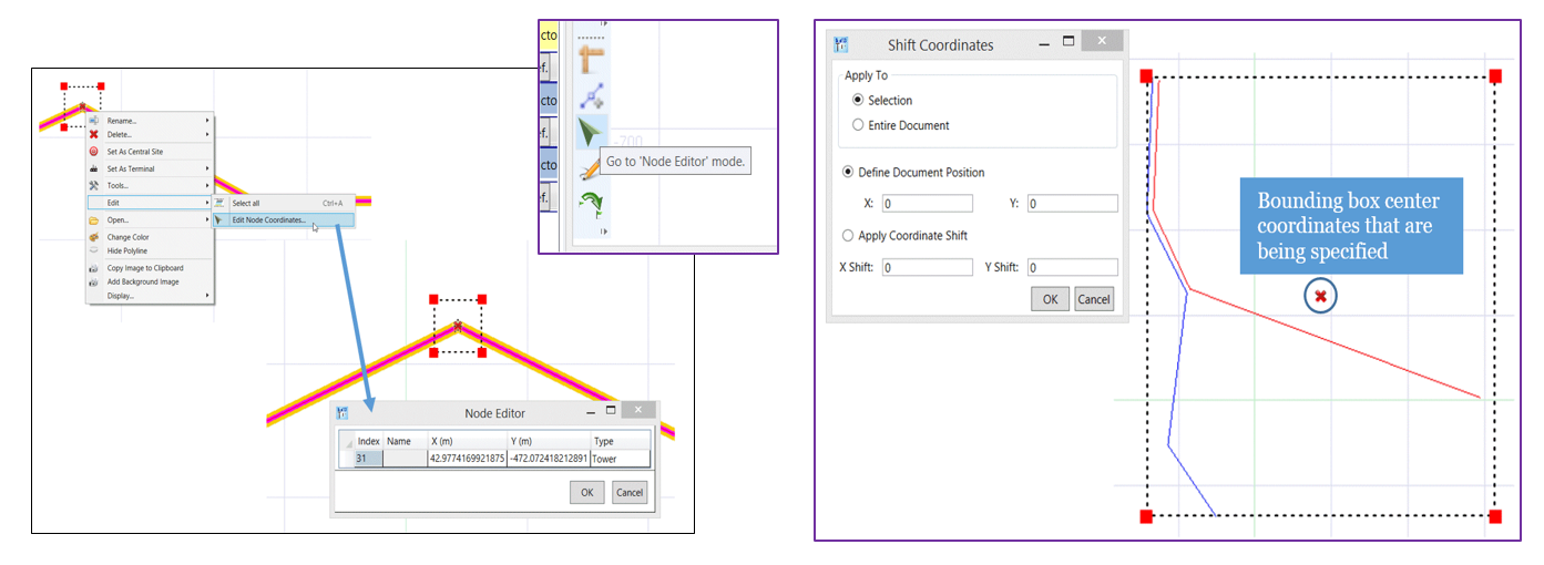
Nodes of polylines can be edited directly from the viewer using the new Node Editor mode, accessible from the viewer toolbar. The entire system or a portion of it can be shifted anywhere.
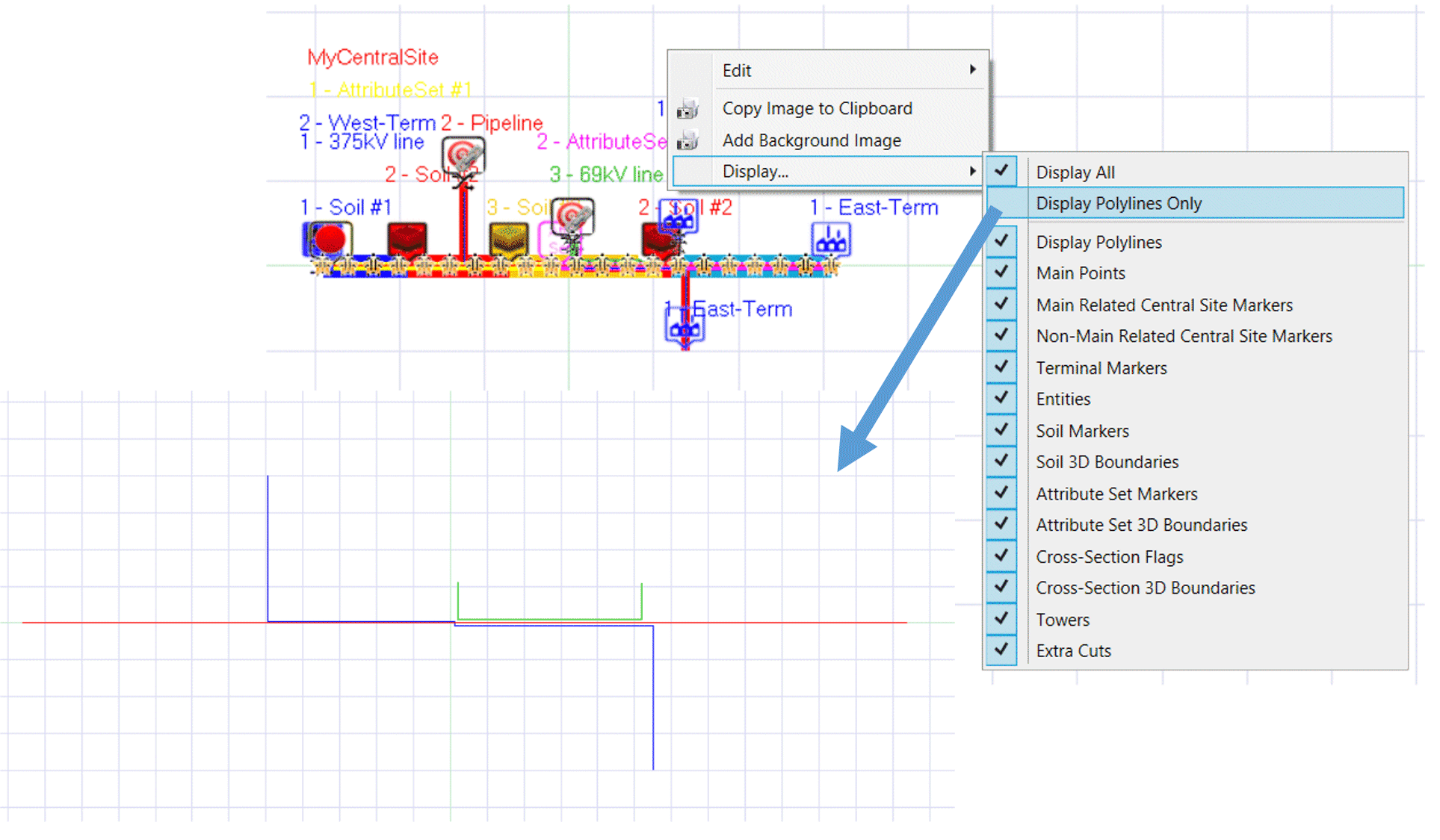
The ROWCAD viewer has shortcuts to turn on or off all visual feedback pertaining to assignments made on polylines (Main Points, Central Site and Central Site Mapping Point markers, Soil markers etc.), or turn it all back on. Simply right-click on the viewer and select Display – Display Polylines Only or alternately Display – Display all.
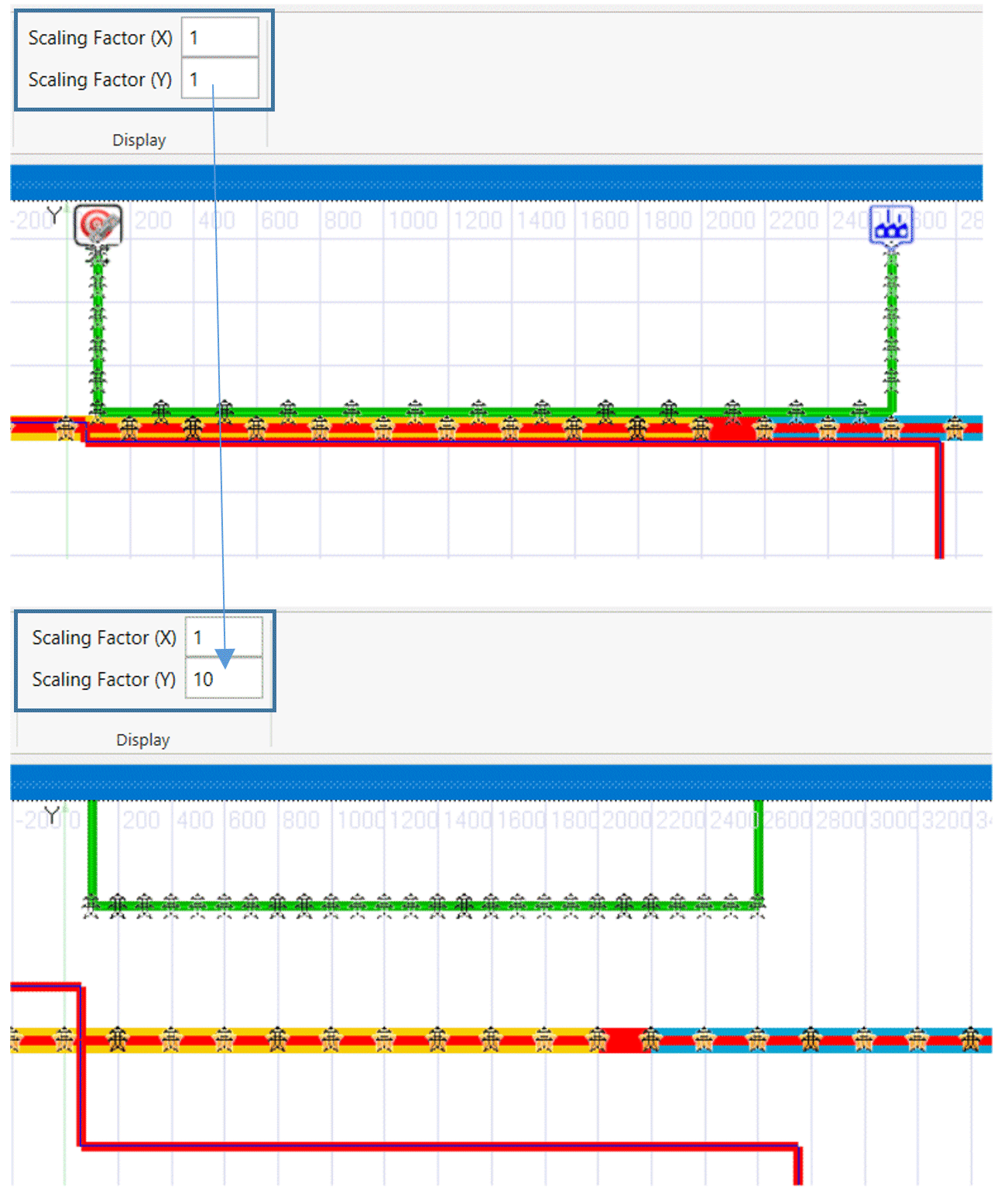
Independent scaling factors can also be defined for the x and y axes views to customize the system view.
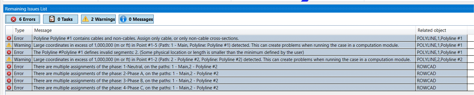
Enhanced Validation of Input Data
A key challenge in designing AC Interference models is the large amount of data that need to be incorporated into a model. The Remaining Issues List has become a central tool in helping find input errors or omissions. Many useful validations have been added to ROWCAD to minimize errors or omissions. These are dynamically tracked, and the Remaining Issues List constantly updated to ensure such issues are addressed as early as possible.