
FCDIST | Simplified Fault Current Distribution Analysis
FCDIST calculates the fault current distribution along shield wires, neutral wires, cable shields and similar metallic paths in multiple terminals, transmission lines and distribution feeders using minimal information and a simple set of data concerning the network. The current division (i.e., split) factor, which is described in the IEEE 80 standard, can easily be determined to alleviate unnecessary conservative requirements on a grounding grid design.
Technical Description
The FCDIST module provides the user with an accurate estimate of the fault current distribution, and hence of the actual fraction of fault current that flows into a grounding system. This can prevent system overdesign and undue expenses, all while maintaining compliance with safety requirements and avoiding unnecessary conservative assumptions regarding the portion of total fault current entering the earth.
Technical Highlights
Fault and unbalanced current distributions are determined by the grounding of the various sections of the transmission and distribution lines and associated substations while accounting for the inductive coupling between the phase wires and any sky, shield or neutral wires. The model created by FCDIST accounts for the following elements:
There is no limit to the number of neutral, sky and shield wires for a given line, so modeling transmission lines equipped with two shield wires or more is an easy task.
The necessary input data is minimal and kept at an easily manageable level by using an equivalent single phase conductor to carry the total unbalance from all three phases (vector sum of all phase currents), and by assuming a uniform line configuration for each block of a given terminal. Computation results are obtained quickly and easily, since the program runs almost instantaneously.
It is relatively straightforward to repeat the computations for each faulted phase conductor (based on the superposition principle) when an equivalent conductor approach is not appropriate.
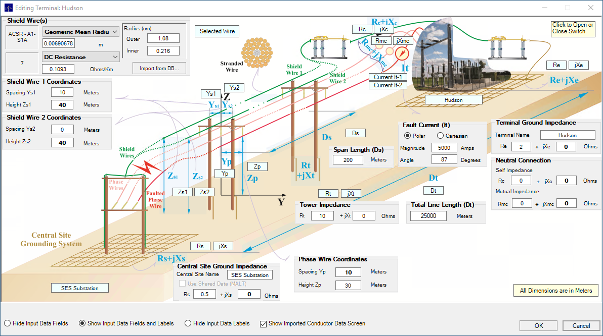
Terminal specification for a transmission line with two shield wires. The shield wires can be dissimilar.
FCDIST supports arbitrary and complex bundles of neutral, sky and shield wires, which leads to accurate evaluations of various parameters, including sheath and armor of cables.
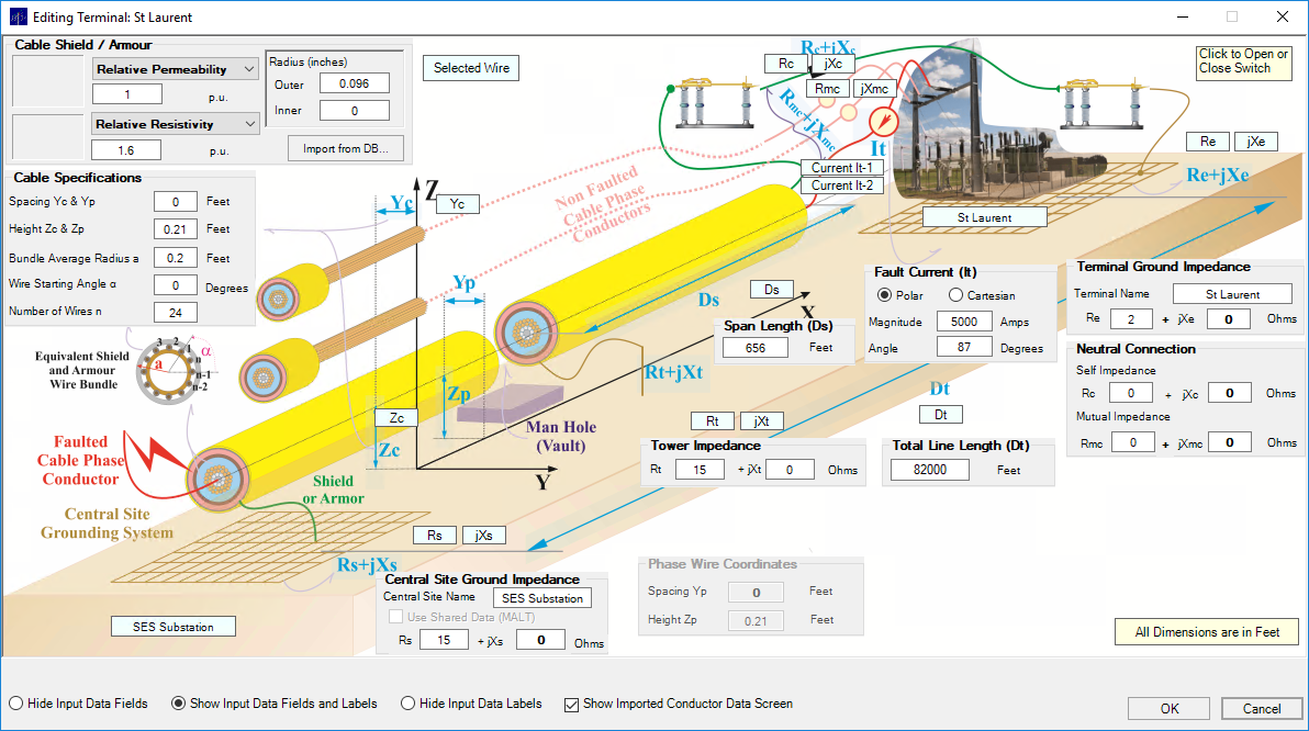
Terminal specification for a power cable.
Technical Features
-
The FCDIST circuit model consists of three basic elements:
- A central site (faulted substation or any transmission line structure).
- Terminal stations (sources of fault currents).
-
Transmission lines connecting the central site to the terminal stations.
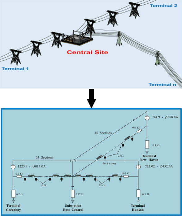
Schematic diagram of the FCDIST circuit model.
- The number of terminal stations and associated transmission lines is unlimited.
- The current sources can be specified with an arbitrary magnitude and phase angle relative to each other.
- For each section of the neutral there is a self impedance, a mutual impedance with respect to the phase wire, and a shunt impedance (representing the towers). The self and mutual impedances can be specified by the user or computed automatically based on the transmission, distribution or cable cross-section information.
- For additional flexibility, the distribution and transmission lines and the neutral, sky and shield wires at the terminal section can be specified with arbitrary series or mutual impedances with respect to the phase wire.
- Users of FCDIST can access the SESLibrary module, which contains data related to thousands of conductors, cables and other components and equipment widely used throughout the power, pipeline and railway industries. Incorporating these predefined parameters into your project can facilitate its execution and completion.
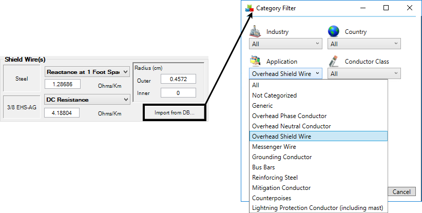
Accessing the SESLibrary module.