Several enhancements have been incorporated into SESConverter. For example, more entities for conversion have been added and also mappings between CAD file and SES file attributes have been improved. In particular the following features are now available:
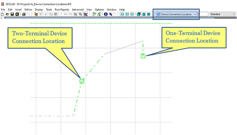
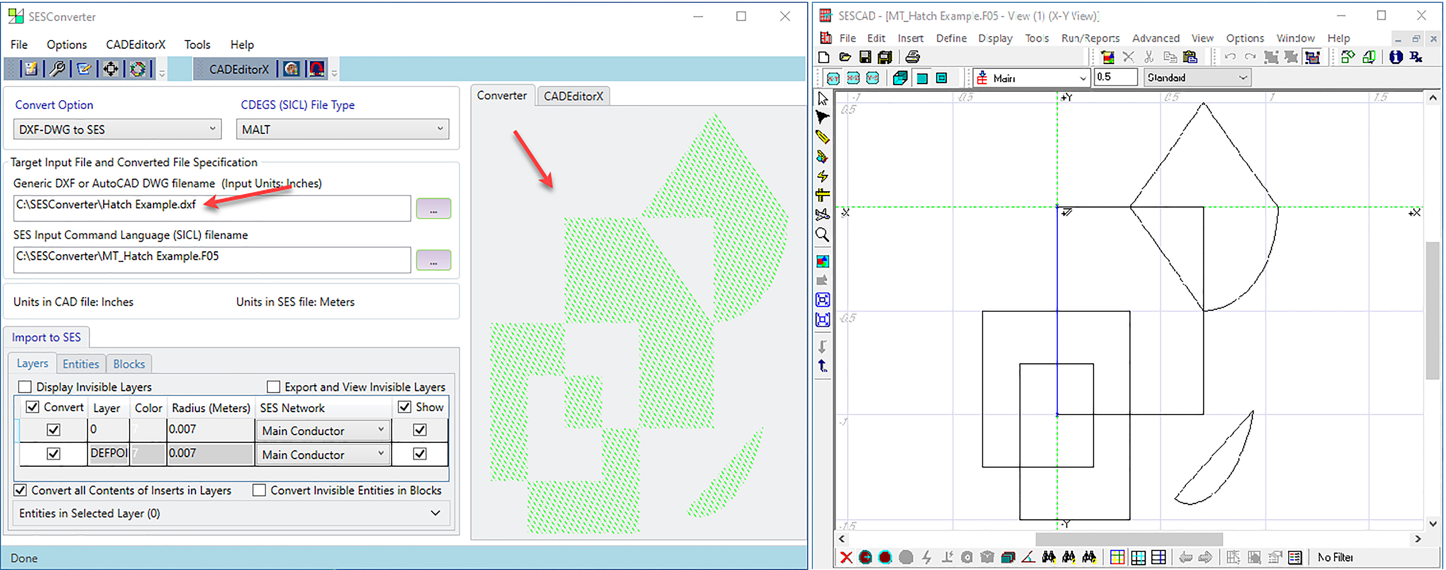
Support for Hatch entities that are sometimes used in CAD drawings for small grounding mats or foundations. The contour of the Hatch is imported as SESConductors.
Figure 28: SESConverter handling Hatch entities from a DXF file.
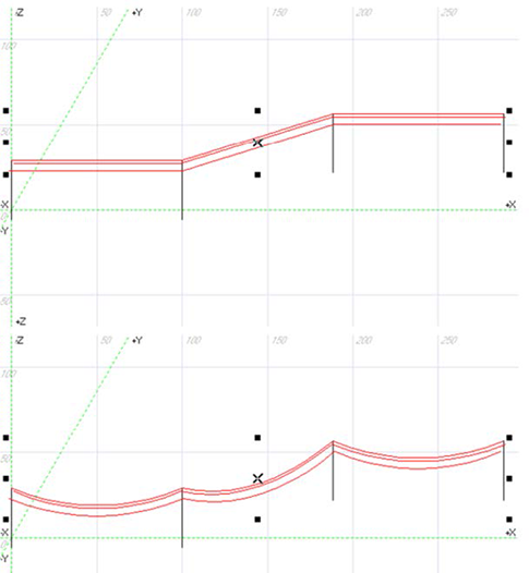
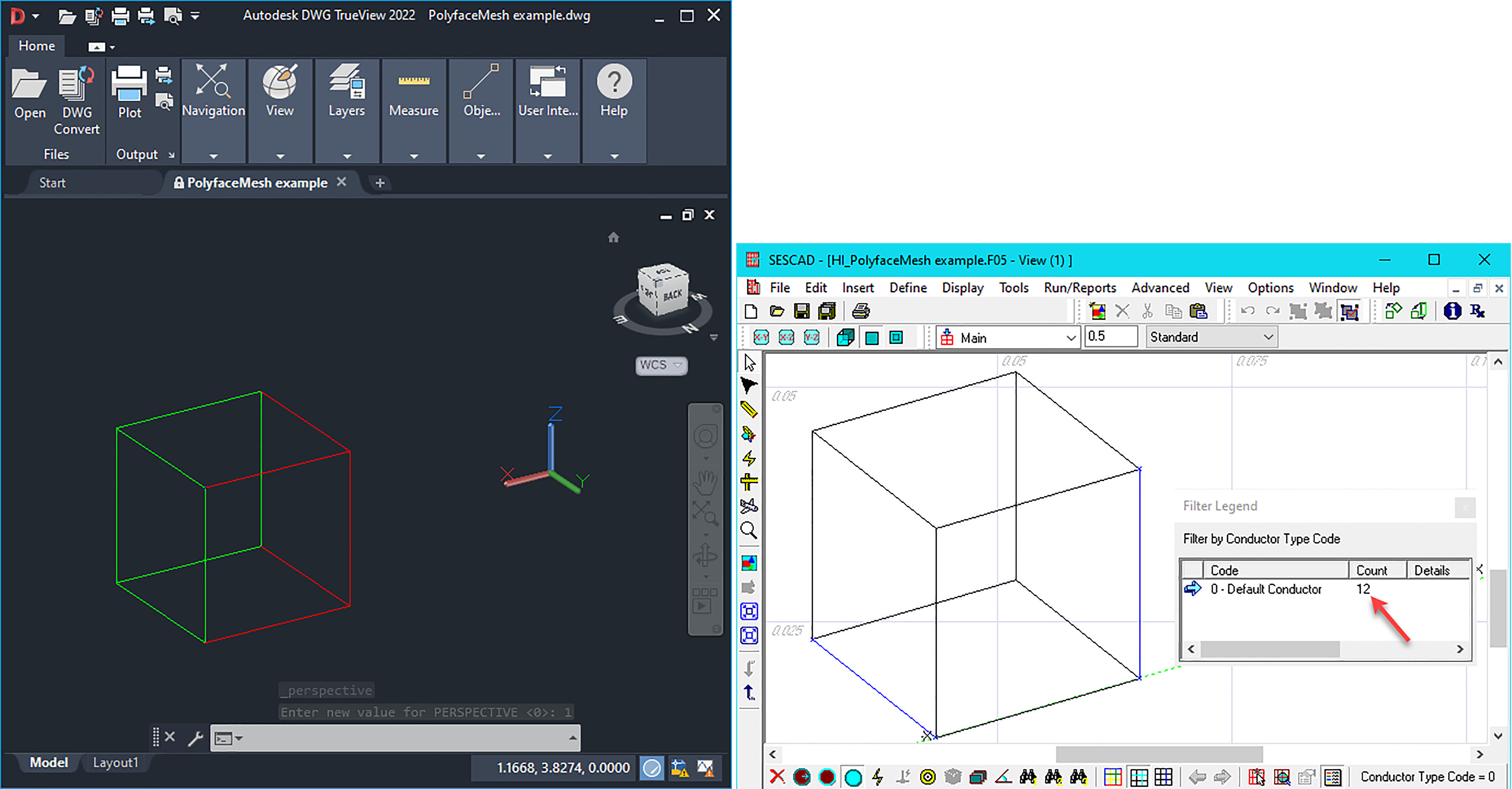
Better import of PolyfaceMesh: SESConverter now detects their possibly overlapping edges and unifies them into a single one.
Figure 29: PolyfaceMesh forming a cube is imported as 12 conductors rather than 24.
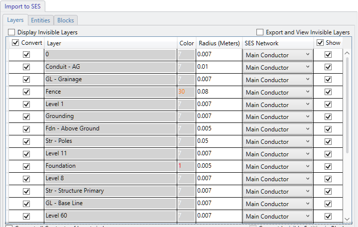
Invisible layers can now be displayed and imported with the same flexibility as visible ones.
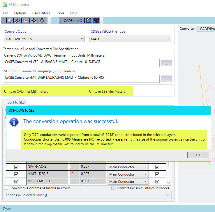
Accidental system resizing and consequential small conductor loss is prevented due to better display of system of units changes and alerting messages.
Figure 30: Messages informing about the units difference between the CAD and
SES files and the consequences on the conversion outcome.
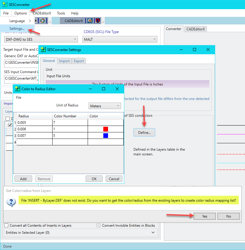
Automatic importing of existing CAD layer colors or SES radii in the Color-to-Radius mapping table.
Figure 31: Colors or radii can automatically be extracted
from the input file to start filling the mapping table.
Clearer Inputs: a read-only look is now given to the data grid columns that contain informational data only, while the editable columns remain with a normal enabled look.
Figure 32: Editable columns (e.g. Radius in Layer Mapping mode) are now visually distinguished from informational columns (Layer and Color) displayed with a read-only look.
For the Layer Radius/Color Mapping, similarly as for the Color Radius Mapping, the program now automatically saves the mapping information in a text file, this time with extension .LDEF. The file can easily be reused by simply copying and renaming it appropriately for the targeted case.
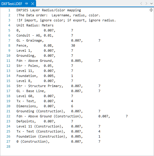
Figure 33: Layer mapping definition file (.LDEF).
Consult the article “Improvements in SESConverter” for more details.
As described in the article entitled “Hot Stuff: Ampacity of Copper-Clad Steel” in this Proceedings, SES has developed a new tool that calculates the ampacity of copper-clad steel with much greater accuracy than the highly simplistic IEEE Standard 80 methodology that has been used in past versions of the SESAmpacity tool.
Having a more accurate tool is important for the grounding system design engineer, who until now was left with the following perplexing sentence in Section 11.3.1 of IEEE Std. 80-2013:
“Independent testing shows the actual short-term fusing currents for a copper-clad steel conductor and a copper-bonded steel ground rod can be different than those calculated by Equation (37) because of the phenomenon of variable heat capacity of steel, explained in note (d) of Table 1.”
The new tool is all the more important as the price of copper skyrockets, resulting in higher levels of copper theft, which incurs both financial losses and safety issues due to missing grounding conductors. Copper-clad steel is becoming the material of choice, due to the theft-deterrence and mechanical strength it provides. The design engineer therefore needs a reliable and accurate means to calculate the ampacity of copper-clad steel.
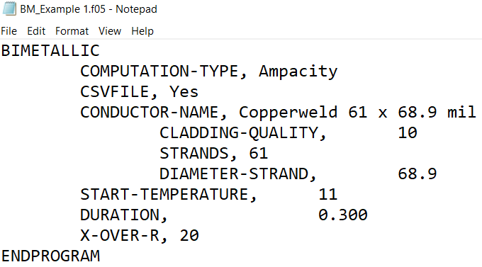
A command-mode version of this tool, named “SESAmpacityBM”, with “BM” referring to “Bimetallic”, is included in this Users’ Group Conference release, as a beta version. A Windows interface is presently under development for CDEGS Version 18. A user’s guide and template input file for the command-mode tool are provided in the UGC release. The input file can be prepared with a text editor, such as Notepad: a sample input file is shown in Figure 34. The calculation can then be run by dragging the input file into SESBatch and launching the thermal simulation. The SESAmpacityBM tool has been tailored to calculate the thermal performance of copper-clad steel, based on data provided by Copperweld Bimetallics.
The following calculations are available:
- Rms fault current that heats the user-specified copper-clad steel conductor from ambient temperature to the maximum allowable temperature (by default, the fusing temperature of copper), for a user-defined fault duration and X/R ratio.
- Fault duration resulting in heating of a user-specified copper-clad steel conductor to the maximum allowable temperature, for a given rms fault current and X/R ratio.
- Maximum temperature resulting from the flow of a user-specified rms fault current and X/R ratio, through a given copper-clad steel conductor, for a given duration.
- Strand size required to limit the maximum temperature to a user-specified value, for a given fault current magnitude, X/R ratio, and fault duration.
Figure 34: Example command mode input file.
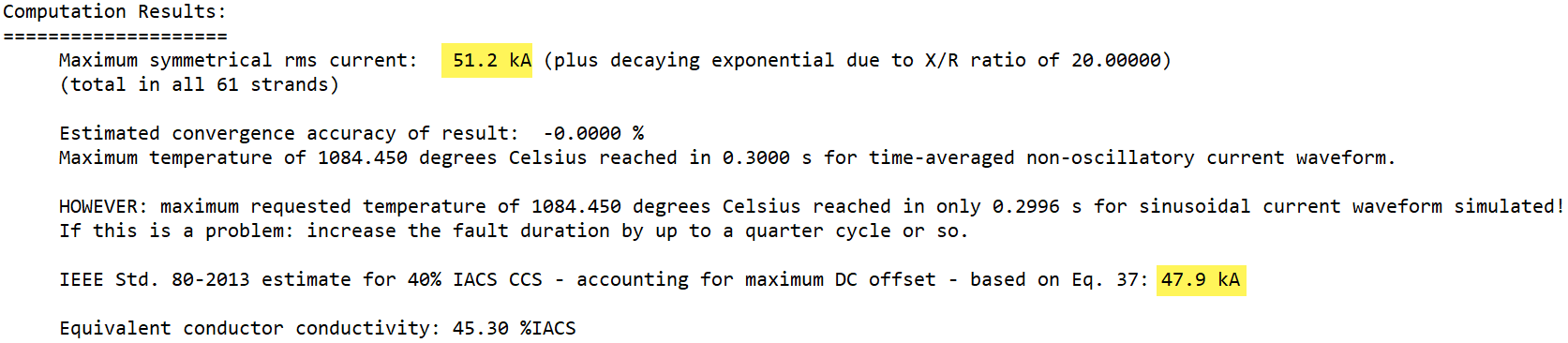
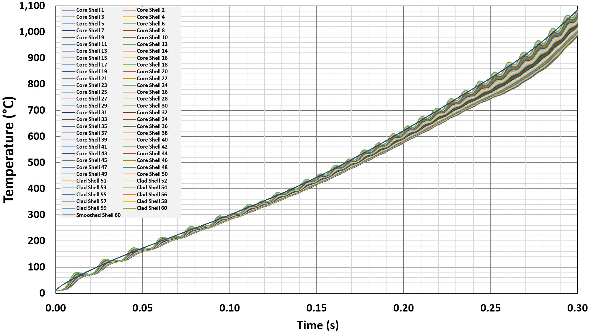
Results are provided in a short summary located in the .F09 output file (see Figure 35 for a sample), with detailed temperature versus time curves in an optional CSV file, which can be used to graph (see Figure 36 for a sample) the evolution of temperature throughout the cross section of each copper-clad steel strand.
Figure 35: Example summary report in command mode output file.
Figure 36: Sample graph of results provided in CSV output file.
See the article entitled “Hot Stuff: Copper-Clad Steel” in this Proceedings for further details.
SESTextEditor
In 2021, SESTextEditor was extended to handle all text file formats, in particular the SES F09 output files. While the advanced searching abilities of the application made it possible to find all standardized warning, error and other informative messages at once in the output files, it remained a search that requires skill with writing regular expressions, in order to be performed efficiently. This is no longer necessary. On loading a F09 file, all such messages are automatically given a colored highlight and wavy underline, for best visibility (see Figure 37). They are also conveniently listed in the application’s Issues List, from which navigation to the corresponding line number is activated by double-clicking an entry. The application’s status bar recalls at all times (i.e. even when the Issues List is hidden) the count of entries in the Errors, Tasks, Warning and Messages categories.
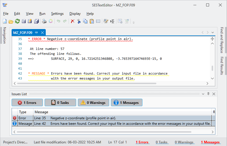
Figure 37: Informative messages color highlight and wavy underline in SES F09 output files. Messages also appear grouped in the Issues List, and their count per category
is displayed in the application’s status bar.
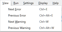
For even more versatile navigation between messages, the Next/Previous Error/Warning feature of the legacy FileView application was reproduced. It is hosted under the View top menu (Figure 38).
Figure 38: Error and Warning messages navigation.
Time performance was kept in mind while developing the parsing of output files to list the contents of messages it contains. An improvement factor of about 20 from the first implementation was achieved such that loading large F09 files remains practically unimpeded.