SESResap
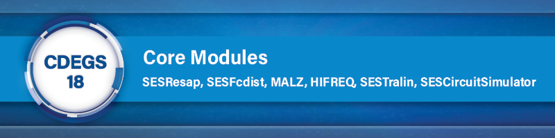
Sorting the soil resistivity data can be particularly useful when they were not measured following an ordered sequence or when data from multiple traverses are combined under a single group. Although the sorting feature was available in previous versions of the application, its use conflicted with usual column selection. The two features were now rendered compatible, with column selection being initiated by a click on the column header and sorting, by a click on a dedicated button appearing when the mouse pointer hovers over the column header (see Figure 1).
Figure 1: Column selection and sorting of data from datagrid column headers.
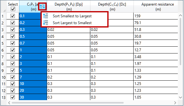
By popular demand, after the completion of a computation run, the RMS Error between the measured and computed apparent resistivities is now displayed in the Computation Results panel, for the Horizontal Layers soil type (see Figure 2).
Figure 2: Display of RMS Error reached for the resulting soil model.
Although this measure of “goodness of fit” has its virtues, it should nevertheless be reminded that no such measure is perfect for every situation. Indeed, the RMS Error is typically satisfactory for single-traverse analysis, but its bias towards lower resistivities becomes more apparent for the case where multiple traverses are analyzed together. It is therefore no substitute for the informed judgment of the grounding engineer who interprets a soil structure not just in terms of its RMS Error, but also incorporates conservativeness considerations inferred from the subsequent intended use for the soil model.
SESFcdist
The work introduced in 2021 on multi-layered components cables was finalized. Such a cable modeling method, contrary to the other methods previously available in SESFcdist, does not rely on the assumption that the outer component be thin and non-magnetic. The user interface was streamlined so that the geometry of cables can be input more simply in terms exclusively of the outer radius of the different layers, while still displaying their inner radius and thickness for information (see Figure 3). The creation or deletion of cable components is managed automatically when adding or removing layers, by detecting well-formed sequences of metallic layers followed by insulating ones. Input data validations were also reinforced to prevent accidental conflicting specifications such as overlapping or non-contacting layers, or metallic-less components. Furthermore, the import of cables from SESLibrary was extended to include GIS/GIL structures as well.
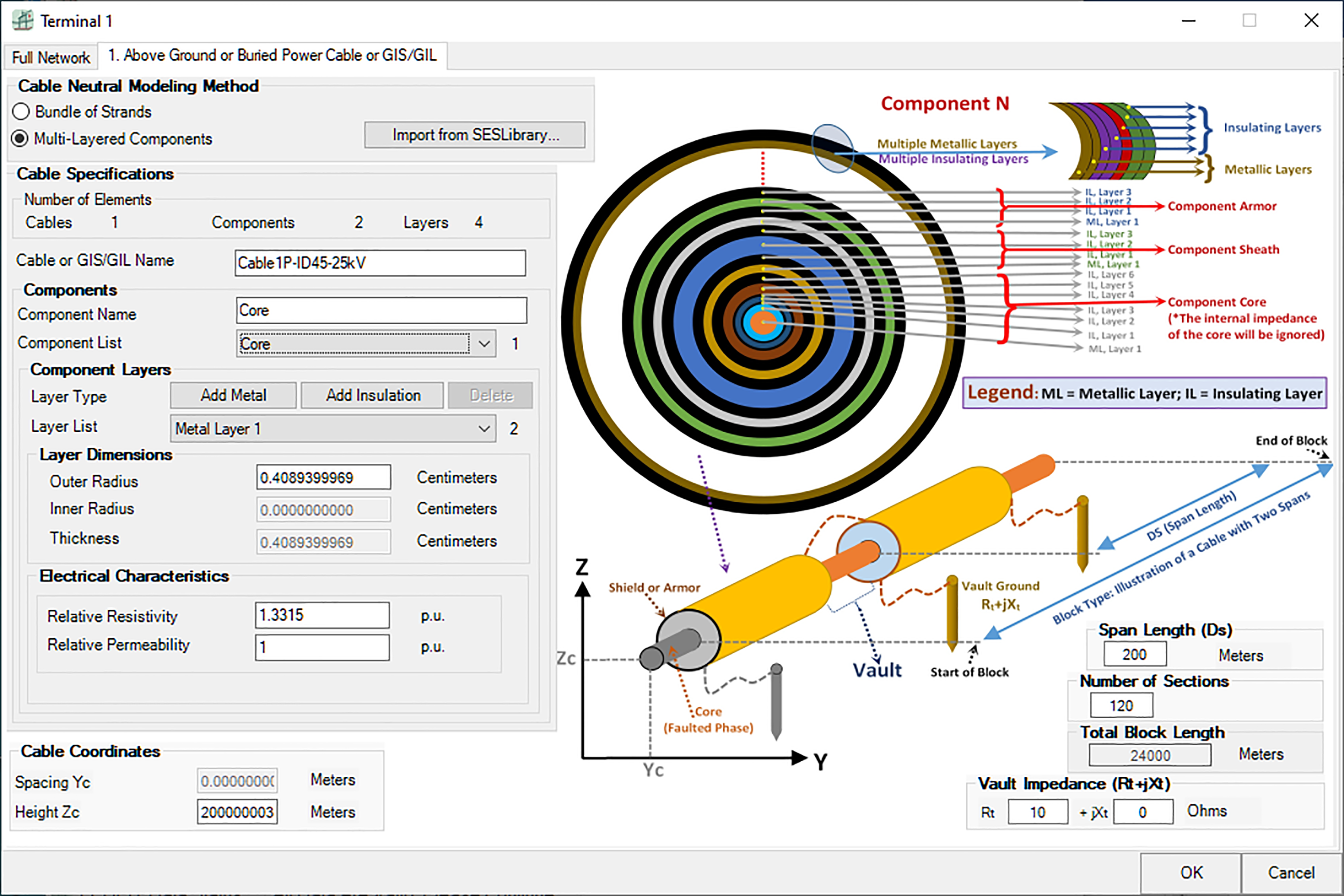
Figure 3: The streamlined interface of multi-layered components
cables in SESFcdist allows for simpler data input.
On the file management side, the creation of new cases now proposes a more appropriate default filename and working directory in-line with that of other SES applications, and a more reliable file backup mechanism was put in place.
MALZ
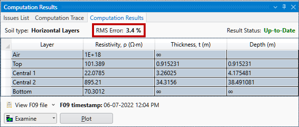
Multi-region soils are useful for Right-of-Way EMI, windfarms and grounding applications. The Multi-Region model available in HIFREQ since 2018 is now also available in MALZ. It gives the same results as HIFREQ at power frequencies, but can conveniently be used also in Right-of-Way and CorrCAD.
Figure 4: HIFREQ and MALZ give same results for potential of two energized grids.
The Multi-Region model uses a simplifying assumption where interface conditions are ignored and the field due to a source is computed using the soil for the source everywhere. This is usually accurate and more accurate models (MRSB, FV MRSB) are under development.
Consult the article “Multi-Region Soil Models in MALZ” for more details.
HIFREQ
- Acceleration in HIFREQ
The time needed to calculate the current distribution in HIFREQ models with a large number of elements (conductor segments or plate patches) has been substantially reduced. A reduction by a factor of two or greater is possible in cases having 2,000 elements or more.
Consult the article “Acceleration of Current Distribution Calculation in HIFREQ” for more details.
- Device Connection Locations
The latest version of HIFREQ introduces the notion of Device Connection Location. A Device Connection Location refers to a virtual network “location” where an arbitrary external device (unknown to HIFREQ) can be physically connected to the HIFREQ network. With Device Connection Locations, the solution for multiple HIFREQ cases – possibly hundreds – differing only by the behavior of the devices can be obtained in about the same time it takes for running a single HIFREQ case! This can be especially useful for parametric analyses where the response of the system is to be obtained for various network conditions that depend on the behavior of the devices.
Consult the article “Device Connection Locations in HIFREQ” for more details.
SESTralin
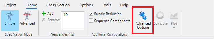
The advanced options that were available in the legacy TRALIN interface are now accessible from the SESTralin ribbon (Figure 5).
Figure 5: Advanced Options are now accessible from the application ribbon.
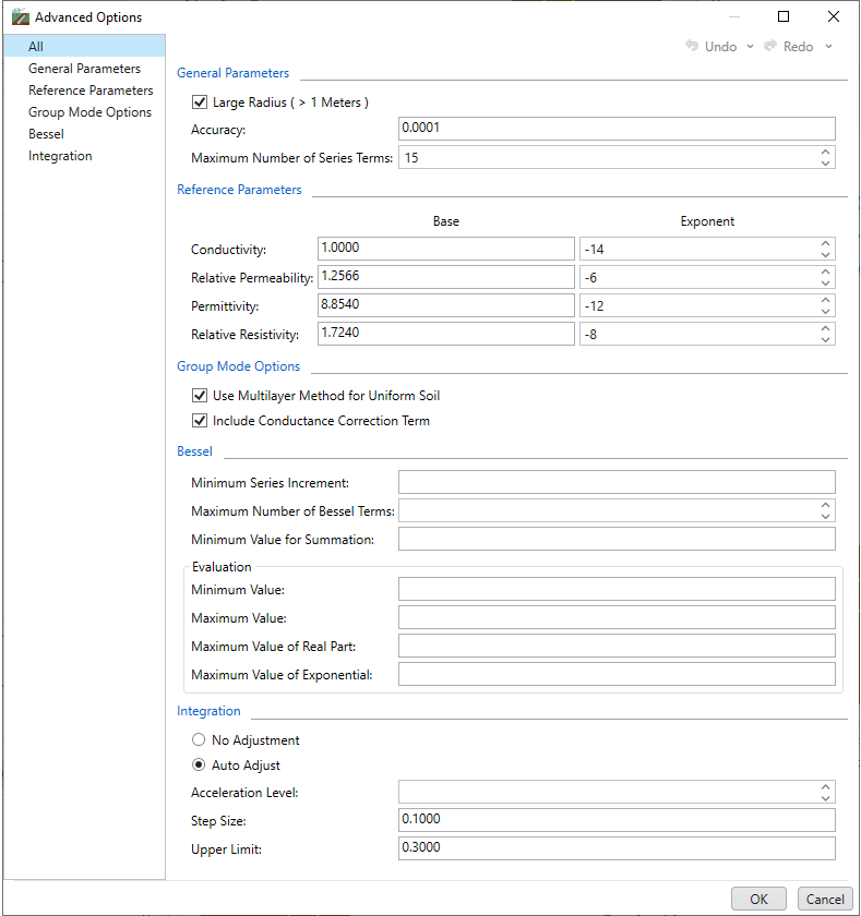
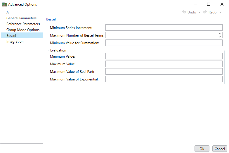
You can display all options simultaneously (Figure 6) or focus on a specific group of options (Figure 7). The screen will display only the options related to that mode of the case, e.g. Group Mode Options are shown in Figure 5 and Figure 6 because the case is defined in Group Mode.
Figure 6: All Advanced Options shown.
Figure 7: Specific group of options shown.
You can now create new components, either directly from the database or from a component type template from Cross-Section tab of the ribbon.
Figure 8: Create new components from the Database or from a component
type template from the Cross-Section tab of the ribbon.
A new feature was introduced in TRALIN Circuit Mode to calculate generalized symmetrical components for system configurations including any number of circuits and any number of phases in each circuit. The new generalized symmetrical component impedance matrices can be useful, for instance, to provide a quick estimate of the relative levels of AC interference induced by the zero sequence and positive sequence currents in a transmission line on a neighboring pipeline.
Consult the article “Generalized Symmetrical Components in TRALIN Circuit Mode” for more
details.
SESCircuitSimulator
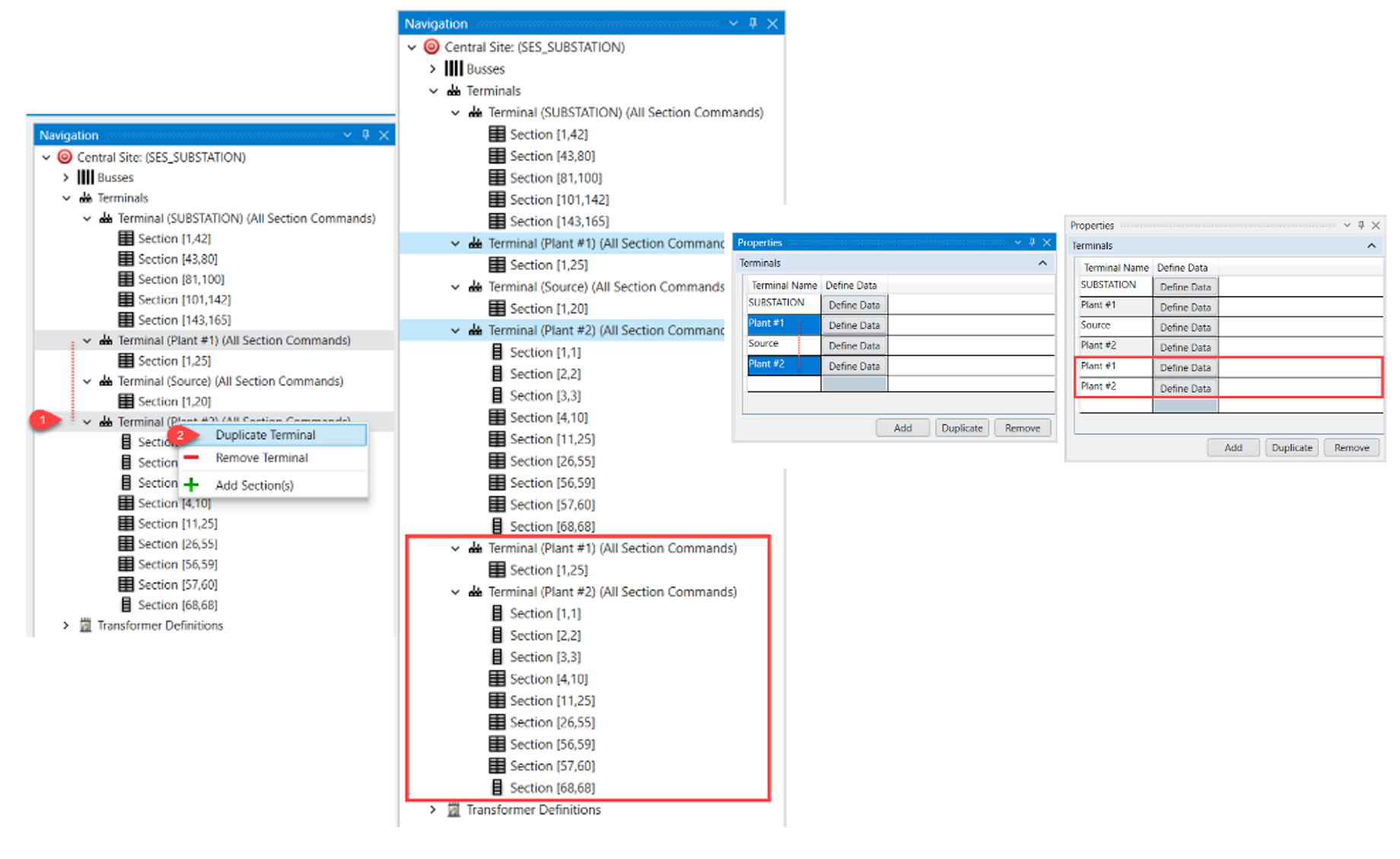
The duplicate action allows duplicating one or several SPLITS commands of the same type in one action. When a SPLITS command is duplicated, all of its subcommands are also duplicated. For instance, if a TERMINAL command contains multiple SECTION data and each section contains SELF and MUTUAL impedances, then duplicating this terminal will result in duplicating all its subcommands (i.e. its sections, self and mutual impedances etc.).
The command data types and their respective subcommands that can be duplicated are: BUSS, TERMINAL (Grounding impedances, Energization, Mutual Impedances, Sections), SECTIONS (Self-Impedances, Mutual and Interconnection impedances), TRANSFORMER (Locations).
Figure 9: Duplicate action via the Navigation panel (left) and the Properties Panel (right).
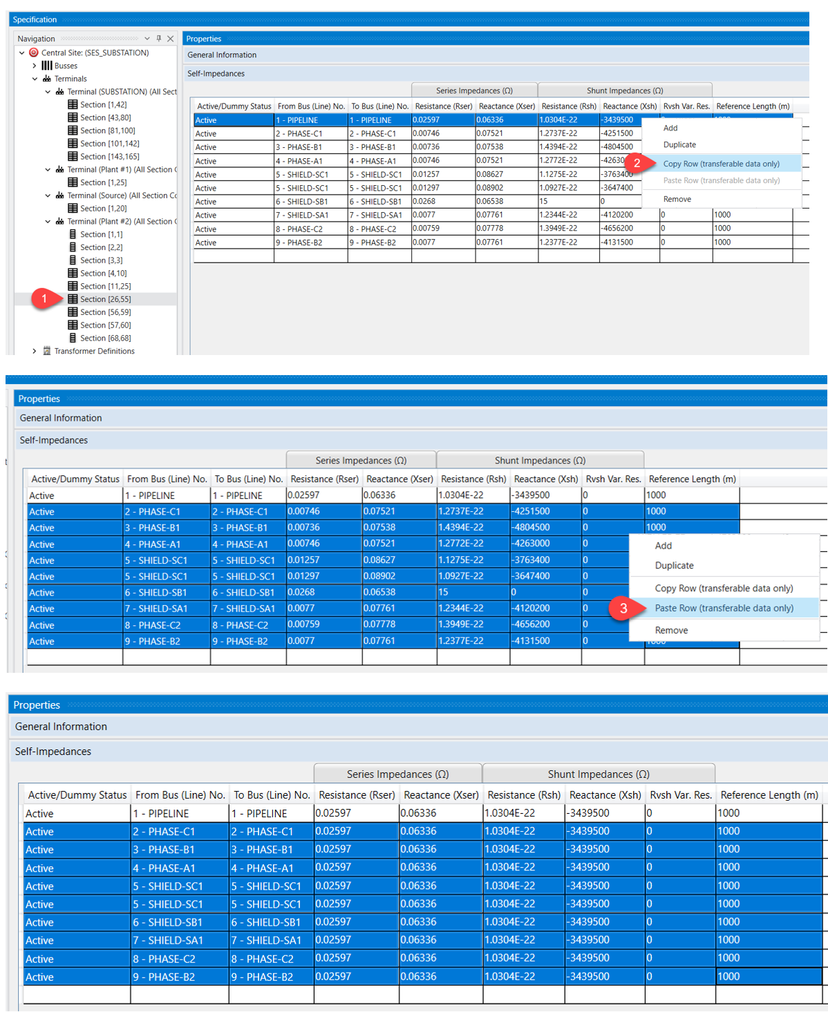
The Copy and Paste actions allow copying data from one or several data field(s) and pasting them into other data fields (usually of the same data type). Note that copy and paste commands perform only on data from a data grid (not via the Navigation panel). The SPLITS command data types that data can be copied from and pasted to are: BUSS, EARTH, LINES, SELF, MUTUAL.
Figure 10: Copy-Paste action of the self-impedance parameters.
|