|
||
HIFREQDevice EditorThe Devices capability in HIFREQ has continued to evolve significantly since its introduction at previous UGC conferences, with major improvements focused on simplifying device configuration workflows, improving scenario management, and enabling the efficient analysis of large electromagnetic networks. A new Device Editor is now available directly in SESCAD, providing a graphical interface for configuring device behavior and managing device scenarios. The Device Editor allows users to define device parameters and operating states for a wide range of device types, including switches, current and voltage sources, and user-specified devices based on external HIFREQ models. Automatic validation of terminal compatibility and current conservation rules helps prevent inconsistent device configurations and simplifies the setup of complex studies. The device workflow can now be used to efficiently segment large HIFREQ networks into multiple independent regions connected through device terminals. In the example presented in this paper, a detailed central study region containing substations, transmission lines, grounding systems, and a parallel buried pipeline is separated from the surrounding transmission network. The peripheral network is solved independently in HIFREQ, generating an F94 response database that is later imported into the central model through a user-specified device. This methodology allows the electromagnetic response of large surrounding networks to be reused without repeatedly solving the complete system. The following figure illustrates the central portion of the network together with the user-specified device representing the external system and the switches used to define the monitor fault scenarios. 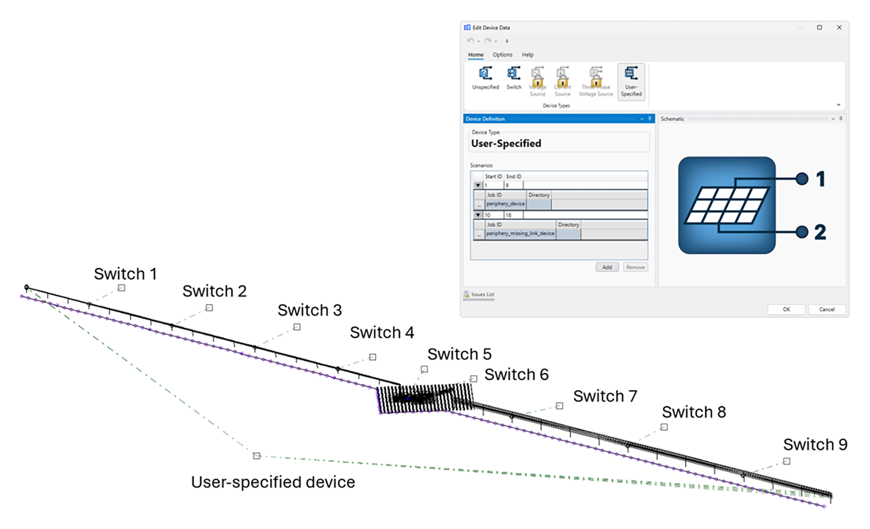
Portion of a network modeled in HIFREQ. The remainder of the network is represented by a user-specified device. Switches are added to perform a monitor fault study. SESResultsViewer now includes a dedicated Devices Options tab allowing users to rapidly switch between scenario result files while preserving visualization settings. Envelope generation capabilities are also available, enabling the automatic computation of minimum, maximum, and average quantities across large groups of scenarios. These features considerably improve the practicality of monitor fault studies and network contingency analyses involving large numbers of operating conditions. See the article entitled “Analyzing Large HIFREQ Networks with Devices” in these Proceedings for further details. Enhanced Plate ModelingModeling of Plates in All Available Layered Soil StructuresThe ability to model metallic plates was introduced many years ago. However, there was a limitation regarding the soil structure in the HIFREQ computation module: the soil model was restricted to include at most two horizontal soil layers in addition to the air layer. This limitation has recently been eliminated, and plates can be modelled in horizontally stratified soils with any number of layers. In addition, plates can now be specified in vertically layered soils as well as multi-region soil structures. Therefore, beginning with SES software Version 21, plates can be modeled in all available stratified soil structures, including:
Additionally, it is now possible to specify metallic plates in soil structures containing finite-volume regions. Junctions Between Multiple Plates with Magnetic Flux OptionAn analysis of the effects of magnetic flux in plates was introduced in Version 20 of SES Software. Beginning with this version, magnetic flux effects in any number of plates can be computed by activating the Magnetic Flux feature under Advanced Options | Plate Settings, a capability restricted to a maximum of two magnetic plates sharing a common edge when accounting for magnetic flux effects in Version 20. Typical examples include shielding enclosures with multiple compartments (i.e., a single enclosure subdivided into shielded regions as shown below) and partitioned shielding systems in high-voltage installations, consisting of multiple shielding sections distributed across different equipment areas and interconnected through common junctions. 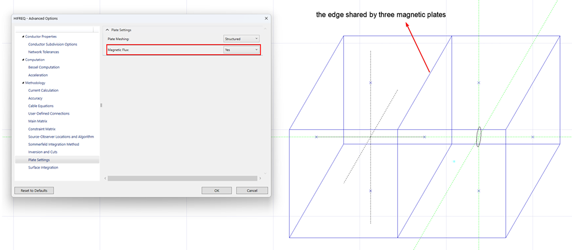
|
||
|
||
|
SES & technologies ltd. 3055 Blvd. des Oiseaux, Laval, Quebec, Canada, H7L 6E8 +1 (450) 622-5000 info@sestech.com ©2026 SafEngServices & technologies ltd. |